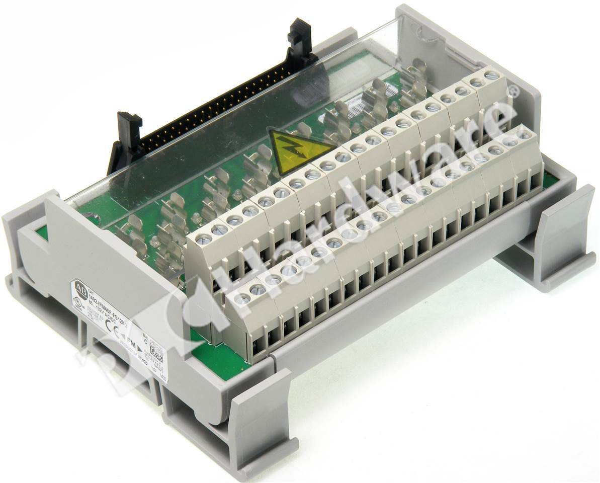
1492-ifm40f-fs-4 Wiring Diagram
Wiring — refer to the label section on page 174. 40 point isolated fusible, digital interface module, 24 volt ac / dc, blown fuse indicators, with fuse clips, 4 terminals per ouput, cat #:
PLC Hardware Allen Bradley 1492IFM40F Series A, New Surplus Open
Compatibility — to ensure proper operation with the i/o module, do not exceed the voltage

1492-ifm40f-fs-4 wiring diagram. Compatibility — to ensure proper operation with the i/o module, do not exceed the voltage and current ratings of the ifm. Compatibility — to ensure proper operation with the i/o module, do not exceed the voltage and current ratings of the ifm. Technical data bulletin 1492 digital/analog programmable controller wiring systems
Digital interface modules ifm fixed. Fs fused isolated dleds n narrow 24 24 volt 120 120 volt 240 240 volt d number of field side wiring terminals. September digital/analog programmable controller wiring systems.
Compatibility — to ensure proper operation with the i/o module, do not exceed the voltage and current ratings of the ifm. Pinout diagram using cable**n3 with ib32 input module. Compatibility — to ensure proper operation with the i/o module, do not exceed the voltage and current ratings of the ifm.
Wiring — refer to the label section on page 174. Literature library | rockwell automation Compatibility — to ensure proper operation with the i/o module, do not exceed the voltage and current ratings.
(reference connector and crimp type pins for connection to i/o wiring. Wiring — refer to the label section on page 181. Wire wire terminal "b" row.
Interface module, digital, fusible, 40 point isolated, 5 x 20 mm fuse clips, 4 terminals per output, cat #: Wiring — refer to the label section on page 174. In addition, ifm40f wiring diagram datasheet, cross reference, circuit and application notes in.
Used AllenBradley Digital Interface Module 1492IFM40FFS1202 Industrial Solutions Authority